Mechanical engineers use SolidWorks a lot to make 3D models, plan setups, and run simulations. It’s one of the best and most famous tools for this job. It has an easy-to-understand interface that makes it simple for engineers to make complicated mechanical designs. SolidWorks makes the process easier and faster, whether you’re creating samples, parts, or kits.
This post will talk about some important lessons, tips, and tricks that will help you get the most out of SolidWorks for mechanical design. These tips will help you get better at design and speed up your work, from learning basic features to more complex methods.
Why Should You Use SolidWorks to Design Machines?
Let’s look at why SolidWorks is such a popular choice for mechanical design before we get into the tips and tricks:
- Interface That Is Easy to Use: SolidWorks has an interface that is easy for engineers to get started with right away.
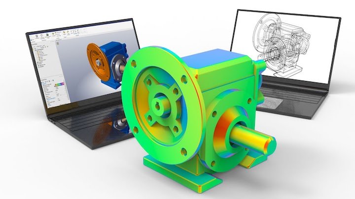
- Strong Simulation: SolidWorks has simulation tools that let you test plans for stress, temperature, and motion before they are made in real life.
- Advanced Assembly Design: SolidWorks makes it simple to plan and control big, complicated groups of hundreds of parts.
- Collaboration and Compatibility: SolidWorks makes it easy for design teams to work together, and the fact that it works with many other CAD and CAM tools makes it an important part of current product development processes.
Here are some great SolidWorks tips, tricks, and how-tos to help you get the most out of it.
1. Getting good at drawing and modelling parts
Sketching is the basis of designing with SolidWorks. When you make a good sketch, it’s easier to model things and fix problems later on in the planning process.
Advice on How to Draw Well:
Use the Sketch Limits: To keep the shape and size links you want, you should always use geometry limits like Horizontal, Vertical, Equal, and Coincident.
The right way to add dimensions is to make sure that your sketches are fully contained by adding dimensions. This will help you keep the part’s shape under control as you design it.
Keep your sketches easy. Begin with basic forms and add more detail over time. Don’t make your first sketches too complicated.
Use the “Offset Entities” tool as a trick.
You can quickly make a similar line, curve, or circle at a set distance from the original entity with the Offset Entities tool. This is especially helpful when making part designs with many levels of shapes or curves.
- How to Make a Simple Part in SolidWork
- Start up SolidWorks and make a new part document.
- Pick up the Sketch tool and pick a plane (Right, Top, or Front).
- Use the Extruded Boss/Base tool to make a simple circle that sticks out.
- Use the Smart Dims tool to give the circle measurements that let you change its size.
- Last, round the circle’s sides with the Fillet tool.
If you follow these steps, you’ll have a simple 3D part that’s ready to be changed further.
2. Effective Modelling of Assemblies
Engineers can work with many parts in one file with SolidWorks’ assemblies, which are one of its main features. Using the right assembly modelling makes sure that the parts fit together correctly and work the way they’re supposed to.
Tips for Designing an Assembly:
Set up subassemblies: When designing a big assembly, break it up into smaller parts. This helps keep things simple and makes sure that you can work on separate parts without changing the whole system.
How to Use Mate Features Correctly: To set the relative places of parts, use Mate features. Mates like Concentric, Parallel, Coincident, and Distance control how the parts in the assembly move and line up.
When you need to make different versions of an assembly with different settings, use Assembly Configurations to make it easy to switch between them.
Use “Mate References” as a trick
Mate References make it easier to build parts by making the matching process easier. By setting up fixed mate references on parts, it’s easy to place and line up components without having to choose mates by hand every time.
How to Put Together an Assembly with Simple Parts
- In SolidWorks, open a new Assembly file.
- Use Insert Components to add parts from your current part files.
- To line up the parts, use the Mate tool. For instance, you could mate two parts concentrically and then use a distance mate to move them around.
- Check how the assembly moves with the Move Component tool to see if the parts move freely as expected.
- Save the structure and make any necessary changes to the parts for the finished design.
3. Using the simulation tools in SolidWorks
SolidWorks has a set of modelling tools that engineers can use to test their ideas online before they make physical models. This helps save time and money by finding design flaws and making them better early on.
How to Do Simulations:
Do a static analysis. First: First, run a Static Simulation to see how your part will react to regular loads. You can add forces and border conditions with the Study tool.
Mesh Correctly: The Mesh is what every program is built on. A fine mesh makes things more accurate but takes longer to calculate, while a wide mesh makes things faster but less accurate. Depending on how hard your plan is, use a balance.
Use Materials from the Library: SolidWorks has a library of materials that already have values set, such as Young’s Modulus, Poisson’s Ratio, and Yield Strength. Using true materials makes it easier to model how things work in the real world.
Advice: To Get It Right, Use “Mesh Refinement.”
If you think the results of your modelling are wrong, try making the mesh more precise around the areas where you think there will be more stress or bending. This will make the game more accurate without having a big effect on how well it works overall.
- Instructions on How to Do a Simple Stress Analysis
- Open the part you want to play out.
- Step 1: Go to the Simulation tab and pick Static Study.
- Fixtures, such as solid or rolling supports, can be used to make the simulation more like the real world.
- Apply a force to simulate the sensation of being under pressure.
- When you click “Run,” you can see the distortion, stress, and factor of safety.
- Please review the results and make any necessary adjustments to the plan to enhance its strength and reduce stress.
4. How to Use Design Tools for Sheet Metal
SolidWorks has special tools for creating parts out of sheet metal. These tools make sure that your plan is best for making parts out of sheet metal, whether you’re making parts or just making prototypes.
When designing with sheet metal, begin with a base flange. Parts made of sheet metal start with the Base Flange feature. You can set the sheet metal’s thickness and size with this tool.
The “Flatten” tool can convert the part’s 3D model into a flat 2D print for production.
Make sure the bend radius is correct. For a sheet metal design to work, the bend radii must match the capabilities of the production process to avoid weak spots in the material.
Use the “Sheet Metal Bend Table” trick.
The Sheet Metal Bend Table helps you change the bend’s radius and length. To ensure your plan works best for production, you can change the bend table based on the material and how it will be made.
Making a Part Out of Sheet Metal: A Guide
- From the Features tab, open a new Part file and pick Sheet Metal.
- Begin by making a Base Flange and deciding on its size and thickness.
- To add more features, use tools like Edge Flange, Hem, and Sketched Bend.
- The Flatten feature lets you see and check the part when it’s flat and ready to be made.
- You can save your plan and then send it as a DXF file so that it can be built.
5. Using add-ins and macros to make SolidWorks your own
You can make your work easier in SolidWorks by adding your own tools, scripts, and add-ins. With these updates, you can simplify boring chores, speed up design work, and make SolidWorks fit your needs perfectly.
How to Make Changes:
Do things over and over again with macros: If you find yourself doing the same thing over and over, make a macro to do it for you. This cuts down on mistakes and saves time.
Explore Add-Ins: SolidWorks has a number of add-ins, such as SOLIDWORKS Electrical, SOLIDWORKS Plastics, and SOLIDWORKS Composer for advanced visualisation, that can help you create better.
Change the Interface: You can change the look of the feature tree, toolbars, and quick keys to make SolidWorks easier to use and speed up the design process.
Use “SOLIDWORKS Task Scheduler” as a trick.
When you add the Task Scheduler add-in, you can set up standard jobs like file changes, batch printing, and system maintenance to run automatically. This saves time and makes things get done faster.
SolidWorks Tutorial: How to Make a Simple Macro
Select Macro > New from the Tools menu.
Make a simple app that will do something automatically, like adding a level or feature.
You can save the script and make it easy to access by assigning it to a keyboard shortcut or a button on the menu.
Run the macro on a new part to make sure it does what you want it to do.
In conclusion
SolidWorks is a strong set of tools for mechanical engineers that can be used for 3D modelling, testing, designing assemblies, and more. You can improve your process, make designs that work better, and reduce mistakes by learning how to use key features, tips, and tricks like drawing, modelling, and sheet metal design.
Whether you are new to SolidWorks or have used it before, learning and experimenting with it will not only improve your skills but also help you become a better mechanical designer. You can use SolidWorks to its fullest and take your engineering projects to new heights if you practise.