
1. Introduction: What Is Shaft Alignment?
Two machines — like a pump and a motor — are connected by a coupling.
Both machines have a shaft. The shaft is the rotating rod that transfers power from one machine to the other.
Shaft alignment means: Both shafts must sit on the same straight centerline.
If the shafts are not in line, they fight each other. One pulls left. The other pulls right. This causes:
- Vibration — the machine shakes during operation
- Bearing failure — bearings wear out fast
- Seal damage — oil or fluid leaks from seals
- Coupling damage — coupling breaks or wears fast
- Motor overload — motor draws more current than normal
- Short machine life — machines fail before their time
In simple words: Bad alignment = more breakdowns + more money wasted.
Good alignment keeps machines running smooth for years.
📘 Suggested Course: Shaft Alignment – Principles and Best Engineering Practices
👉 If you want to avoid costly misalignment issues and learn precise alignment techniques used in real industrial environments, this course is highly recommended.
👉 Learn accurate shaft alignment methods here: [https://trk.udemy.com/vDZjNd]
2. What Is Laser Shaft Alignment?
Simple Definition:
- Laser shaft alignment is a method where a laser beam is used to check and correct the position of two shafts.
- A laser tool is mounted on the shafts. It sends a laser beam from one side to the other. A sensor reads the beam position. A display screen shows how much misalignment is there and how to fix it.
Manual Alignment vs. Laser Alignment
| Point | Manual Alignment | Laser Alignment |
|---|---|---|
| Tool used | Straight edge, feeler gauge, dial indicator | Laser tool with display unit |
| Accuracy | Low to medium | Very high (0.001 mm level) |
| Time needed | More time | Less time |
| Skill needed | High skill | Medium skill |
| Rework | Common | Rare |
| Result | Depends on technician skill | Consistent every time |
Benefits of Laser Alignment:
- Very accurate — reads up to 0.001 mm
- Faster — saves 50–70% of alignment time
- Clear display — tells you exactly how much to move
- Less rework — get it right in fewer tries
- Report generation — some tools print an alignment report
- Works on live thermal growth — accounts for machine heat expansion
📘 Suggested Course: Laser Shaft Alignment – Reliability Engineering
👉 Proper shaft alignment is critical to avoid vibration, bearing failure, and energy loss in rotating equipment.
👉 Learn precise alignment techniques used in real industries: [https://trk.udemy.com/rE2DaQ]
3. Five Easy Methods Used in Industries:
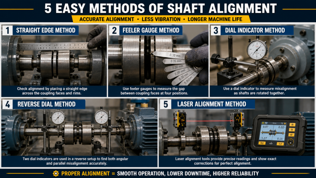
Method 1: Straight Edge Method:
How It Works:
- Place a straight metal ruler or rod across the top of both coupling halves.
- Look at the gap between the straight edge and coupling face.
- If there is a gap on one side, the shafts are not aligned.
Steps:
- Place straight edge on top of coupling
- Check if it sits flat on both sides
- Check the side gap too
- Add or remove shims under the machine feet to correct it
- Repeat until the straight edge sits flat
Where It Is Used:
- Old machines in small workshops
- Quick rough checks in the field
- Where no other tools are available
Limitation:
- Very low accuracy (only ±0.5 mm level)
- Cannot measure angular misalignment properly
- Depends on how good the straight edge is
- Not suitable for high-speed machines
Method 2: Feeler Gauge Method:
How It Works:
- After rough alignment, small gaps remain between the coupling faces.
- A feeler gauge is a set of thin metal blades. Each blade has a marked thickness (e.g., 0.05 mm, 0.10 mm, 0.20 mm).
- You insert blades into the gap to measure it.
Steps:
- Rotate coupling slowly and check all four positions — top, bottom, left, right
- Insert feeler gauge blades into the gap between coupling faces
- Note the gap readings at each position
- The difference between readings tells the angular misalignment
- Correct by adding or removing shims
Where It Is Used:
- Combined with straight edge for basic checks
- Small pumps and low-speed equipment
- Quick field checks
Limitation:
- Cannot measure offset misalignment accurately
- Difficult in tight spaces
- Readings change with coupling wear
- Accuracy depends on technician’s touch and experience
📘 Suggested Course: Pump and Motor Basics, Selection and Optimization (HVAC)
👉 If you want to clearly understand pump selection, motor sizing, and how to optimize HVAC system performance in real-world applications, this course is highly recommended.
👉 Learn practical HVAC pump & motor concepts here: [https://trk.udemy.com/oNyL4b]
Method 3: Dial Indicator Method:
How It Works:
- A dial indicator is a small gauge with a needle that moves when you push its tip.
- You mount it on the shaft using a magnetic bracket. Then you rotate both shafts together. The needle moves and shows the misalignment reading.
Steps:
- Mount magnetic bracket on one shaft
- Attach dial indicator to bracket
- Touch the dial tip to the other coupling rim
- Set the dial to zero at the top (12 o’clock position)
- Rotate both shafts together — 90°, 180°, 270°, 360°
- Note readings at each position
- Calculate the correction needed
- Add or remove shims, tighten bolts
- Recheck and confirm
Where It Is Used:
- Medium-speed pumps, fans, compressors
- Most general industrial machines
- Standard maintenance in many factories
Limitation:
- Bracket sag causes reading errors
- Readings must be calculated manually
- Needs experience to read correctly
- Takes more time than laser method
Method 4: Reverse Dial Method:
How It Works:
- This is an improved version of the dial indicator method.
- Two dial indicators are used — one on each shaft. Both face each other.
- This removes the error caused by bracket sag. Readings are more accurate.
Steps:
- Mount one dial on shaft A, facing shaft B’s rim
- Mount another dial on shaft B, facing shaft A’s rim
- Rotate both shafts together
- Take readings at top, bottom, left, right positions
- Use the reverse dial formula to calculate corrections
- Apply corrections with shims
- Recheck both dials
Where It Is Used:
- Higher accuracy jobs
- Large pumps, compressors, gearboxes
- Where dial indicator method is not accurate enough
Limitation:
- Two dials and two brackets needed
- Manual calculation is complex
- Still less accurate than laser alignment
- Setup takes more time
📘 Suggested Course: Bearing Course – From Zero to Failure Analysis
👉 If you want to understand bearing basics, failure analysis, and real-world troubleshooting used in industries, this course is highly recommended.
👉 Learn practical techniques here: [https://trk.udemy.com/R06nG9]
Method 5: Laser Alignment Method:
How It Works:
- This is the most accurate and modern method used in industry today.
- Two laser units are mounted on the two shafts. One unit sends a laser beam. The other unit has a sensor to receive it.
- When you rotate the shafts, the sensor reads the beam position and calculates misalignment automatically.
The display screen shows:
- How much misalignment exists (in mm)
- Which foot needs to be raised or lowered (in mm)
- Green/red light showing if alignment is OK or not
Steps:
- Mount laser units on both shafts
- Connect to display unit or smartphone app
- Enter machine dimensions (distance between feet, coupling center distance)
- Rotate shafts to 3 positions (or some tools need only 3 clicks)
- Read the display — it shows exact correction values
- Add or remove shims as shown
- Rotate again and confirm — display shows green
Where It Is Used:
- All modern industries — power plants, oil & gas, chemical plants, paper mills
- High-speed machines (above 3000 RPM)
- Critical equipment where downtime is expensive
Limitation:
- Tool is expensive (basic tools start from ₹50,000–₹3,00,000+)
- Needs basic training to operate
- Laser units can be damaged if dropped
- Battery life must be checked before use
4. Step-by-Step Laser Shaft Alignment Procedure:
This is the most important section. Follow every step carefully.
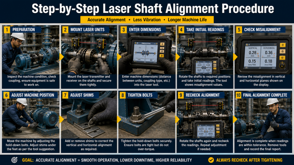
Step 1: Pre-Check Before Starting:
Before you touch the alignment tool, check the machine condition first.
Check these things:
- Base condition — Is the machine base plate clean and flat? Is it cracked or corroded? If the base is not good, alignment will never hold.
- Foundation bolts — Are all foundation bolts present? Are they rusted or loose? Replace any damaged bolts before alignment.
- Coupling condition — Check coupling rubber elements, spider inserts, or disc packs. Replace worn coupling parts before alignment.
- Shaft condition — Check for shaft runout. Rotate the shaft slowly by hand. It should rotate smoothly without wobble.
- Bearing condition — Listen for any rough sound. If bearings are bad, fix them first. Don’t align on bad bearings.
📘 Suggested Course: Complete Geometric Dimensioning & Tolerancing (Ultimate GD&T)
👉 If you want to master engineering drawings, tolerances, and real-world manufacturing standards, this course is highly recommended.
👉 Learn GD&T concepts step-by-step with practical examples: [https://trk.udemy.com/7XJOaA]
Step 2: Soft Foot Check (Very Important — Never Skip This):
What is soft foot?
- When a machine has four feet, all four must sit flat on the base. If one foot is not touching properly — that is called a soft foot.
- Even 0.05 mm soft foot can destroy your alignment after tightening.
How to check soft foot:
- Tighten all four foundation bolts properly
- Mount a dial indicator on the machine frame (near one foot)
- Loosen that foot bolt while watching the dial
- If the dial moves more than 0.05 mm — soft foot is present
- Repeat for all four feet
- Correct by adding a shim under the soft foot
- Recheck until all feet show less than 0.05 mm movement
Types of soft foot:
- Parallel soft foot — one foot is shorter than others (fix with flat shim)
- Angular soft foot — foot is twisted or bent (fix with tapered shim)
- Squishy soft foot — dirt or paint under the foot (clean the base)
Step 3: Rough Alignment:
Before using the laser tool, do a quick rough alignment by eye or straight edge.
- The two shafts should be roughly in line — within 2–3 mm
- This saves laser measurement time
- Place a straight edge across coupling and adjust roughly
- Rough alignment gets you close. Fine alignment gets you perfect.
Step 4: Mount Laser Units:
- Clean the shaft surface where laser unit will be clamped
- Mount laser unit (transmitter) on the driver shaft (motor side)
- Mount sensor unit (receiver) on the driven shaft (pump side)
- Make sure both units are clamped tight — no wobble
- Check that both units are at the same clock position (both at 12 o’clock)
- Connect display unit or Bluetooth to smartphone if applicable
- Enter machine data:
- Distance from front foot to coupling center
- Distance from front foot to rear foot
- Distance between the two laser units
Step 5: Take Measurements:
- Rotate both shafts slowly together
- Stop at three positions as instructed by the tool (usually 9 o’clock, 12 o’clock, 3 o’clock — or tool gives beep)
- Some tools need only a single 180° sweep
- The display calculates and shows:
- Vertical offset (up/down)
- Horizontal offset (left/right)
- Angular misalignment (angle difference between shafts)
- Shim values — how much to add or remove at each foot
📘 Suggested Course: Machine Design Basics – I (Shaft, Bearings & Gears)
👉 If you want to build a strong foundation in shaft design, bearing selection, and gear fundamentals used in real industrial applications, this course is highly recommended.
👉 Learn machine design concepts step-by-step: [https://trk.udemy.com/5k7Zkj]
Step 6: Vertical Correction (Shim Adjustment):
The display tells you: “Add 0.15 mm shim at front feet” or “Remove 0.10 mm from rear feet.”
- Loosen the machine hold-down bolts
- Lift the machine slightly using a jack or pry bar
- Add or remove shims as shown on display
- Lower machine back down
- Tighten bolts in a star pattern — not one by one
- Take a new laser reading to confirm
Step 7: Horizontal Correction:
- Loosen the hold-down bolts slightly (do not remove)
- Use a soft-faced mallet or jack bolts to move machine sideways
- Move by the amount shown on display
- Tighten bolts and recheck
Step 8: Final Tightening Sequence:
This step is often done wrong. Follow this correctly:
- Tighten one bolt slightly → move to opposite bolt → tighten slightly
- Go in a star or cross pattern — never in a circle
- Do 2–3 tightening passes, increasing torque each time
- Final torque must match the manufacturer’s spec
- After final tightening, take one last laser reading
- Confirm the display shows green / values within tolerance
Step 9: Final Check and Record:
- Record before and after alignment readings
- Mark the shim thickness at each foot with a marker pen or tag
- Fill in the alignment report / job card
- Sign off the work
📘 Suggested Certification: Certified Maintenance & Reliability Technician (CMRT)
👉 If you want to build a strong foundation in maintenance, troubleshooting, and reliability practices used in real industries, this certification is highly recommended.
👉 Start your CMRT preparation here: [https://trk.udemy.com/aNWANZ]
5. Technical Values and Tolerances:
This is real practical data. Learn these numbers.
Acceptable Misalignment Range (General Guide):
| Type | Acceptable Limit | Corrective Action Needed |
|---|---|---|
| Offset (Parallel) | 0.05 mm – 0.10 mm | Below 0.05 mm is ideal |
| Angular | 0.05 mm/100 mm | Less is better |
| Soft Foot | Less than 0.05 mm | Any more — must correct |
RPM-Based Tolerance Guide:
This is very important. Faster machines need tighter alignment.
| Speed (RPM) | Max Offset (mm) | Max Angular (mm/100mm) |
|---|---|---|
| Below 1000 RPM | 0.15 mm | 0.10 |
| 1000 – 3000 RPM | 0.10 mm | 0.07 |
| 3000 – 6000 RPM | 0.05 mm | 0.04 |
| Above 6000 RPM | 0.02 mm | 0.02 |
Note: Always check the coupling manufacturer’s alignment tolerance first. These are general industry values.
What Happens If Values Exceed Limits?
- Excessive vibration starts immediately after startup
- Bearings heat up and fail within days or weeks
- Mechanical seal fails — fluid leaks
- Coupling wears out fast — rubber elements crack
- Motor draws more current — trips on overload
- Shaft can crack over time under cyclic stress
Why Tolerance Matters:
- Think of it like a car tyre alignment. Even 1° wrong — your tyre wears on one side and fuel efficiency drops.
- Same with shafts. Even 0.1 mm wrong — machines start suffering.
- Tight tolerance = long machine life + low maintenance cost.
6. Small Parts Used During Alignment:
These small items are just as important as the big tools. Don’t ignore them.
A). Shims:
- What it is: Thin metal plates, usually stainless steel, in different thicknesses (0.05 mm, 0.10 mm, 0.25 mm, 0.50 mm, 1.0 mm).
- Why used: Placed under machine feet to raise the machine to the correct height. Laser tool tells you the exact shim thickness needed.
Tip: Always use stainless shims — they don’t compress or corrode. Never use aluminum foil or cardboard as shims. That causes problems later.
B). Foundation Bolts (Hold-Down Bolts):
- What it is: The large bolts that hold the machine to the base plate.
- Why important: If these are loose or corroded, alignment will shift after startup. Always check bolt condition before aligning. Replace corroded or stretched bolts.
C). Coupling Bolts:
- What it is: Bolts that connect the two coupling halves together.
- Why important: Coupling bolts must be tightened evenly. Uneven torque causes coupling distortion and misalignment. Use a torque wrench. Tighten in a star pattern.
D). Dial Bracket / Magnetic Stand:
- What it is: A magnetic base with adjustable arm that holds the dial indicator on the shaft or machine body.
- Why important: A loose bracket gives wrong readings. Always check that the magnetic base is gripping tightly. Check bracket sag before taking readings.
E). Spacer:
- What it is: A metal ring or block placed between the coupling halves.
- Why used: On some machines, the motor and pump are far apart. A spacer coupling is used to fill the gap. Spacer length must be measured accurately for correct alignment calculation.
F). Feeler Gauge:
- What it is: A set of flat metal blades with marked thicknesses.
- Why used: To measure small gaps — between coupling faces, under machine feet (soft foot check), or between components. Very useful even when using a laser tool for quick gap checks.
G). Laser Sensor Mounting Chain / Strap:
- What it is: The chain wrap or V-clamp that holds the laser unit on the shaft.
- Why important: If the chain is loose, the laser unit wobbles during rotation and gives wrong readings. Always pull the chain tight and lock it properly. Check before each measurement.
7. Tools Used for Shaft Alignment:
A). Laser Alignment Tool:
- The main tool. A set of two units — transmitter and receiver — with a display unit.
- Popular models: TKSA 41 (SKF), TKSA 11, Easy-Laser XT550, Pruftechnik Rotalign.
- The SKF TKSA 41 is very popular in Indian industries. It is easy to use, has Bluetooth, and gives a detailed report. Price range: approx. ₹1,50,000–₹2,50,000 (varies by dealer and year).
B). Dial Indicator:
- A mechanical gauge that measures movement in 0.01 mm or 0.001 mm steps. Used with a magnetic bracket. Cost: ₹500–₹3,000 for basic models.
C). Feeler Gauge Set:
- A pack of thin blades from 0.05 mm to 1.0 mm. Used for soft foot checks and gap measurements. Cost: ₹200–₹800.
D). Straight Edge / Precision Ruler:
- A flat, straight metal bar used for quick rough alignment checks. Used across coupling faces or shaft ends.
E). Torque Wrench:
- Used for tightening coupling bolts and foundation bolts to the correct torque. Very important to avoid over-tightening or under-tightening.
F). Shim Set (Stainless Steel):
- Pre-cut shims in standard sizes to fit under machine feet. Available in sets with various thicknesses.
G). Rubber Mallet / Soft-Face Hammer:
- Used to tap the machine sideways for horizontal correction without damaging machine surface.
8. Common Mistakes to Avoid:
Mistake 1: Skipping the Soft Foot Check:
- This is the most common mistake. Technicians rush to take laser readings without checking soft foot.
- Result: After you tighten the bolts, the machine shifts. Alignment is lost. You have to start over.
- Fix: Always check soft foot first. Always.
Mistake 2: Not Replacing Worn Coupling Parts:
- If the coupling insert or rubber spider is worn out, the coupling has play (loose movement). Laser readings will jump and be inconsistent.
- Fix: Replace worn coupling parts before alignment.
Mistake 3: Wrong Shim Placement:
- Using the wrong shim thickness. Stacking too many thin shims instead of one thick shim. Mixing shim materials.
- Fix: Use the exact thickness shown by the laser tool. Use stainless shims. Never stack more than 3–4 shims at one foot.
Mistake 4: Not Following the Tightening Sequence:
- Tightening bolts in a circle or tightening one bolt fully before others.
- This twists the machine and shifts the alignment after you’ve done all the work.
- Fix: Always use a cross/star pattern. Do 2–3 passes at increasing torque.
Mistake 5: Skipping the Final Recheck:
- After tightening, always take one more laser reading. Machines can shift slightly when bolts are tightened.
- Fix: Never skip the final reading. Confirm green on the display before closing the job.
Mistake 6: Not Accounting for Thermal Growth:
- Hot machines grow taller when running. A pump aligned cold may go out of alignment when hot.
- Fix: For hot machines, apply a pre-set correction (offset downward) based on the manufacturer’s thermal growth data. Most laser tools have this feature built in.
9. Safety Tips:
A). Lockout / Tagout (LOTO) — Never Skip This:
Before doing any alignment work, the machine must be electrically isolated.
- Switch off the motor at the local isolator
- Lock the isolator with your personal padlock
- Put a “Do Not Start” danger tag on the isolator
- Verify zero energy — press the start button to confirm the motor does not start
This is not optional. This is a life-saving rule.
B). Avoid Rotating Parts:
- Never put your hand near a rotating coupling or shaft
- Even at slow rotation during alignment checks, keep fingers away
- Wear close-fitting clothes — no loose sleeves near rotating parts
C). Use PPE (Personal Protective Equipment):
- Safety shoes — always in the plant area
- Safety glasses — when grinding shims or working near couplings
- Gloves — when handling sharp shim edges or feeler gauges
- Hard hat — in areas with overhead equipment
D). Safe Use of Laser Tool:
- Do not look directly into the laser beam
- Most alignment lasers are Class 2 (low power) but still avoid eye exposure
- Handle the laser units carefully — they are precision instruments and can be damaged by dropping
10. Real Industrial Example:
Problem: Pump Bearing Failure Every 3 Months
- Machine: 15 kW motor driving a centrifugal water pump
- Problem reported: The pump bearing was failing every 3 months. High vibration. Mechanical seal leaking. High electricity consumption.
Investigation:
- Technician measured the shaft alignment with a laser tool.
Result:
- Vertical offset: 0.42 mm (Limit: 0.10 mm) — WAY OUT
- Angular misalignment: 0.18 mm/100 mm (Limit: 0.07 mm) — OUT
- Soft foot found at rear left foot: 0.12 mm — Must correct
The machine had never been properly aligned since installation. Workers had just replaced bearings every time they failed and not fixed the root cause.
Correction Steps:
- Fixed soft foot first — added 0.12 mm shim at rear left foot
- Took fresh laser readings
- Added 0.35 mm shim at front feet (vertical correction)
- Moved motor 0.25 mm to the left (horizontal correction)
- Tightened bolts in star pattern with torque wrench
- Final reading: Offset 0.03 mm, Angular 0.03 mm/100 mm — GREEN
Result After Alignment:
- Vibration dropped from 8.2 mm/s to 1.4 mm/s
- Motor current dropped by 1.8 Amps
- Bearing life improved — no failure in 18 months after alignment
- Mechanical seal stopped leaking
Lesson: The alignment was the root cause. Fix the root cause, not just the symptom.
11. Conclusion:
Shaft alignment is not a complicated job once you understand the basics.
Start with a pre-check. Fix soft foot. Do a rough alignment. Then use your dial indicator or laser tool for fine alignment. Follow the correct tightening sequence. Do a final recheck. Record your results.
The five methods — straight edge, feeler gauge, dial indicator, reverse dial, and laser alignment — each have their place. For most industrial machines today, laser alignment is the best choice for accuracy and speed.
Good alignment saves bearings, seals, couplings, and motors. It reduces vibration, noise, and energy use. Most importantly, it reduces downtime and maintenance costs.
Start with simple machines. Practice the procedure. Build confidence. Then move to bigger, critical machines.
Alignment is a skill. The more you do it, the better and faster you get.