
Introduction:
A pump runs fine for six months. Then one morning it trips on high vibration. You pull it apart and find the coupling chewed up, the bearing races pitted, and the mechanical seal leaking. The root cause? Nobody checked the shaft alignment before the last reinstall.
This happens in plants every day — refineries, power generation facilities, food processing, chemical processing. Misalignment is one of the top three causes of premature rotating equipment failure, right alongside unbalance and lubrication issues.
The dial indicator shaft alignment method has been the backbone of industrial alignment work for decades. Laser alignment tools have their place, but dial indicators are still trusted, affordable, and effective when used correctly. On many job sites across the U.S., they’re the go-to tool — especially in tight spots where a laser target won’t fit.
This tutorial walks through the complete procedure, the way experienced alignment technicians actually do it in the field.
📘 Suggested Course: Shaft Alignment – Principles and Best Engineering Practices
👉 If you want to avoid costly misalignment issues and learn precise alignment techniques used in real industrial environments, this course is highly recommended.
👉 Learn accurate shaft alignment methods here: [https://trk.udemy.com/vDZjNd]
👉 Get full subscription access: https://trk.udemy.com/PzKGrq
What Is the Dial Indicator Shaft Alignment Method?
The dial indicator method — sometimes called the rim and face method or reverse indicator method — uses mechanical dial gauges to measure the relative position of two shaft centerlines.
You mount a bracket on one shaft and swing a dial indicator around the other shaft’s rim (outside diameter) and face (end). As the shaft rotates, the gauge reads the runout — the deviation from a perfect circle. Those numbers tell you how far off the shafts are and in which direction.
There are two common configurations:
- Rim and Face Method: One indicator reads the rim, another reads the face of the coupling or shaft flange. Good for shorter spans.
- Reverse Indicator Method: Two dial indicators, each reading the opposite shaft’s rim. Preferred for longer spans and considered more accurate because it eliminates face runout error.
In most U.S. industrial facilities, you’ll see the reverse indicator method used on motors, pumps, compressors, fans, and gearboxes.
Tools Required Before Starting Alignment:
Don’t show up to an alignment job without the right gear. Here’s what you need on the workbench before you touch anything:
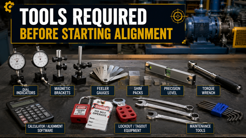
- Dial Indicators: Use a good quality 0.001″ resolution dial indicator. Don’t use a worn-out gauge — the needle should return to zero cleanly after each rotation. Most technicians carry at least two.
- Magnetic or Shaft-Mount Brackets: A solid bracket matters more than most people think. Bracket sag directly causes reading error. Measure sag before every job and compensate for it.
- Feeler Gauges: You’ll use these to check soft foot and to verify shim installation. Keep a quality set with blades from 0.001″ to 0.030″.
- Shim Packs: Pre-cut stainless steel shims in a range of sizes — 0.001″, 0.002″, 0.003″, 0.005″, 0.010″, 0.020″, 0.030″. Brass shims work too but stainless holds up better under load.
- Straight Edge and Precision Level: Good for a quick pre-check of rough misalignment before you set up the gauges.
- Lockout/Tagout Equipment: Non-negotiable. Locks, tags, hasps, and a verified energy isolation checklist before any work begins.
- Calculator or Alignment Software: Some technicians use pre-printed correction tables. Others use mobile apps or simple calculators for shim math.
- Torque Wrench: Required for proper bolt torque during final verification. Guessing on bolt torque is one of the most common causes of post-alignment soft foot.
📘 Suggested Course: Laser Shaft Alignment – Reliability Engineering
👉 Proper shaft alignment is critical to avoid vibration, bearing failure, and energy loss in rotating equipment.
👉 Learn precise alignment techniques used in real industries: [https://trk.udemy.com/rE2DaQ]
👉 Get full subscription access: https://trk.udemy.com/PzKGrq
7 Easy Steps for Accurate Dial Indicator Shaft Alignment Method:
Step 1: Lockout and Isolate the Equipment:
Before you touch the coupling or pick up a wrench, the equipment must be fully de-energized, locked out, and tagged out.
That means:
- Disconnect the motor at the breaker
- Drain pressure from connected piping if applicable
- Verify zero energy with a voltage tester
- Apply personal lock and complete your facility’s LOTO procedure
Common Mistake: Technicians sometimes skip verifying the lock because they “did it themselves.” Always verify energy isolation independently — visual confirmation only.
Field Tip: On larger motors with multiple voltage supply sources, check every terminal block. Some facilities have redundant feeds that don’t show up on older P&IDs.
Step 2: Check Soft Foot Condition:
Soft foot is a condition where one or more of the machine’s feet don’t make full contact with the baseplate. It’s one of the biggest sources of alignment error — and most technicians either rush through it or skip it completely.
To check soft foot:
- Snug all four hold-down bolts (don’t fully torque them yet)
- Mount a dial indicator on the machine frame and zero it
- Loosen one bolt at a time while watching the indicator
- Record the reading before retightening that bolt
- Repeat for all four feet
A reading greater than 0.002″ indicates soft foot that needs correction before proceeding.
Common Mistake: Checking soft foot after inserting shims — that’s backwards. Check it first on the bare feet, correct it, then proceed to alignment.
Field Tip: Parallel soft foot is fixed with shims. Angular soft foot (where only one corner of a foot is high) usually requires shimming under that corner only. Don’t add full shims under angular soft foot — it will make it worse.
📘 Suggested Course: Pump and Motor Basics, Selection and Optimization (HVAC)
👉 If you want to clearly understand pump selection, motor sizing, and how to optimize HVAC system performance in real-world applications, this course is highly recommended.
👉 Learn practical HVAC pump & motor concepts here: [https://trk.udemy.com/oNyL4b]
👉 Get full subscription access: https://trk.udemy.com/PzKGrq
Step 3: Install Dial Indicators Correctly:
This step makes or breaks your readings.
Mount the alignment bracket solidly to the shaft or coupling hub. Use shaft-clamp style brackets where possible — magnetic bases flex too much under their own weight.
Measure bracket sag:
- Mount the bracket with the gauge pointing straight up (12 o’clock), zero the indicator
- Rotate the setup to 6 o’clock (bottom position)
- Read the indicator — this negative number is your sag value
- Add this sag correction to your bottom reading on every job
A typical bracket sag can range from -0.002″ to -0.020″ depending on the span. Ignoring sag gives you inaccurate bottom readings every time.
Common Mistake: Over-tightening the dial indicator stem or mounting it at an angle. The stem must be perpendicular to the surface it’s reading. An angled cosine error will throw off your readings.
Field Tip: Mark all four clock positions — 12, 3, 6, and 9 o’clock — directly on the coupling with a paint marker. It keeps your readings consistent when both shafts are rotated simultaneously (which is the correct technique for reverse indicator setups).
Step 4: Measure Vertical Readings:
Set both indicators to zero at the 12 o’clock position. Rotate both shafts together 180° to the 6 o’clock position and record both readings.
For reverse indicator method, you now have:
- Top reading (T) = 0 (zeroed)
- Bottom reading (B) = your indicator reading ± sag correction
Calculate vertical misalignment:
Total Indicator Runout (TIR) = Bottom Reading − Top Reading
Divide TIR by 2 to get the offset at that measurement plane.
Common Mistake: Rotating only one shaft instead of both together. When the shafts aren’t connected, both must be rotated simultaneously to eliminate any runout from the coupling hubs themselves.
Field Tip: Take three sets of readings and average them. If your readings aren’t repeatable within 0.001″–0.002″, something is wrong — bracket is loose, soft foot wasn’t corrected, or the shaft has runout.
📘 Suggested Course: Bearing Course – From Zero to Failure Analysis
👉 If you want to understand bearing basics, failure analysis, and real-world troubleshooting used in industries, this course is highly recommended.
👉 Learn practical techniques here: [https://trk.udemy.com/R06nG9]
👉 Get full subscription access: https://trk.udemy.com/PzKGrq
Step 5: Measure Horizontal Readings:
Rotate back to 12 o’clock, verify the indicators return to zero (or close to it). If they don’t, repeat.
Now rotate to 3 o’clock (right side) and 9 o’clock (left side), recording each reading.
Horizontal TIR = Left reading − Right reading (with sign)
This gives you the side-to-side offset. Unlike vertical corrections (shims), horizontal corrections are made by sliding the machine feet laterally.
Common Mistake: Forgetting to check for mechanical constraints before making horizontal moves. Piping connected directly to the pump casing can restrict movement and create false corrected-alignment readings.
Field Tip: Before making any horizontal move, loosen all four hold-down bolts and check that the machine slides freely. If it doesn’t, look for foreign material under the feet or corroded baseplate surfaces.
Step 6: Calculate Shim Corrections:
This is where technicians without strong math confidence sometimes go wrong. Take your time here.
For vertical corrections using the reverse indicator method:
- You have two dial indicator readings — one at each shaft
- You know the distance between measurement planes (span between indicator mounting points)
- You know the distance from each measurement plane to the machine feet
The basic formula calculates how much shim is needed at the front and rear feet to correct both the offset and the angularity simultaneously.
Standard formula layout:
Front foot correction = (A × D1) / L Rear foot correction = (A × D2) / L
Where:
- A = misalignment value at measurement plane
- D1, D2 = distance from plane to front/rear feet
- L = span between measurement planes
Most experienced technicians keep a pocket notebook with the machine dimensions for every critical piece of equipment in their area. It saves significant time on repeat alignments.
Common Mistake: Adding shims without removing the old shim pack first. Always pull existing shims, measure the actual thickness with a micrometer, and replace with the correct calculated pack. Guessing on existing shim thickness compounds errors.
Field Tip: Never use more than five shims under one foot. More than five and you introduce the risk of shim walk and thermal instability. If you need more than 0.100″ of shimming, check whether the baseplate itself has settled or if the machine needs to be repositioned.
📘 Suggested Course: Complete Geometric Dimensioning & Tolerancing (Ultimate GD&T)
👉 If you want to master engineering drawings, tolerances, and real-world manufacturing standards, this course is highly recommended.
👉 Learn GD&T concepts step-by-step with practical examples: [https://trk.udemy.com/7XJOaA]
👉 Get full subscription access: https://trk.udemy.com/PzKGrq
Step 7: Perform Final Verification:
After installing shims and making horizontal corrections, torque all hold-down bolts to spec — in a cross pattern, in two passes.
Then re-check your dial indicator readings.
Acceptable tolerances vary by coupling type and operating speed, but a common industry standard for general industrial equipment:
| RPM Range | Offset Tolerance | Angularity Tolerance |
| < 1800 RPM | 0.003″ max TIR | 0.001″ per inch |
| 1800–3600 RPM | 0.002″ max TIR | 0.0005″ per inch |
| > 3600 RPM | 0.001″ max TIR | 0.0002″ per inch |
Re-check soft foot after final torquing. It’s common for soft foot to return slightly after shimming.
Common Mistake: Calling it done after one pass. Always rotate the shaft one full revolution after final torquing and take a fresh set of readings. Bolt tightening can shift the machine slightly.
Field Tip: Document everything. Record before-alignment readings, corrections made, and after-alignment readings. A job record protects you and builds a history that helps predict when equipment will need re-alignment.
Common Shaft Alignment Mistakes That Cause Repeat Failures:
Alignment issues tend to repeat in plants for the same reasons:
- Not correcting soft foot first: Every other step is wasted if the machine rocks on its feet. Soft foot is the foundation — fix it first.
- Bracket sag not accounted for: This is the number-one source of error in dial indicator work. Measure sag on every setup without exception.
- Thermal growth not factored in: Many pumps and motors operate at temperatures significantly different from ambient. At 200°F, a standard carbon steel motor frame grows vertically. If you don’t apply a thermal growth correction offset at cold alignment, the machine will be misaligned at operating temperature. Coupling manufacturer specifications typically provide thermal growth tables.
- Piping strain: Piping connected to the pump casing exerts forces that shift the machine after alignment. This is especially common when insulated steam piping contracts after a cold shutdown.
- Using damaged coupling hubs: Worn or bent coupling hubs create false runout. Always inspect hubs before mounting indicators.
📘 Suggested Course: Machine Design Basics – I (Shaft, Bearings & Gears)
👉 If you want to build a strong foundation in shaft design, bearing selection, and gear fundamentals used in real industrial applications, this course is highly recommended.
👉 Learn machine design concepts step-by-step: [https://trk.udemy.com/5k7Zkj]
👉 Get full subscription access: https://trk.udemy.com/PzKGrq
Dial Indicator Method vs. Laser Alignment Method:

| Factor | Dial Indicator Method | Laser Alignment Method |
| Accuracy | ±0.001″ with good technique | ±0.0001″ typical |
| Cost | Low ($50–$500 for gauges) | High ($3,000–$15,000+) |
| Ease of Use | Requires practice and math skill | Software does the math automatically |
| Field Application | Works in any environment including tight confined spaces | Needs line-of-sight, can struggle in high-vibration areas |
| Skill Requirement | Medium to high | Low to medium |
| Training Time | Weeks to become proficient | Days |
| Battery/Power Needed | None | Yes |
| Best For | Plants with budget constraints, field technicians, non-critical equipment | High-speed critical equipment, large rotating machinery trains |
The bottom line: laser alignment is faster and eliminates human math error. Dial indicator alignment, done correctly, is still fully acceptable for most industrial rotating equipment. Many reliability engineers use both — laser for critical trains, dial indicator for general maintenance work.
Safety Notes During Shaft Alignment:
These are non-negotiable on any job site:
- Always complete LOTO before touching any equipment: No exceptions. The coupling is not a safe handhold when the machine can start.
- Wear proper PPE: safety glasses, steel-toed boots, and gloves when handling shims and tools.
- Beware of stored energy: springs, compressed air lines, and charged capacitors in VFDs can injure even after electrical lockout.
- Don’t work under suspended loads: If a machine is lifted for shimming, block it mechanically before working under it.
- Check for hazardous materials: Pumps handling chemicals may require respiratory protection and chemical-resistant gloves for the coupling inspection portion.
- Verify atmospheric conditions: in confined spaces before entering to take measurements.
📘 Suggested Certification: Certified Maintenance & Reliability Technician (CMRT)
👉 If you want to build a strong foundation in maintenance, troubleshooting, and reliability practices used in real industries, this certification is highly recommended.
👉 Start your CMRT preparation here: [https://trk.udemy.com/aNWANZ]
👉 Get full subscription access: https://trk.udemy.com/PzKGrq
Best Practices From Industrial Maintenance Teams:
Experienced maintenance teams in U.S. process plants follow a few habits that separate them from the average crew:
- Build a machine data card for every critical rotating asset: Include shaft diameters, coupling hub dimensions, distance between measurement planes, and foot-to-coupling distances. Laminate them and hang them in the shop. It eliminates the need to measure dimensions every time.
- Pre-cut shim packs before the job: On planned outages, cut all anticipated shims ahead of time. This cuts alignment time significantly during short turnaround windows.
- Re-align after the first week of operation: New machines and rebuilt equipment often settle after initial run-in. A check alignment at the first scheduled PM is good practice.
- Use a dedicated alignment logbook: Record every alignment job — before readings, corrections, final readings, date, and technician name. Over time, this data shows trends: if a pump needs re-alignment every three months, there’s a larger problem like a failing baseplate, piping strain, or process resonance.
- Check coupling condition every time: While you have the coupling apart, inspect the element — disc pack, elastomer insert, grid, or gear teeth. Replace on condition, not just on schedule.
FAQ:
Q: How accurate is the dial indicator shaft alignment method compared to laser alignment?
- With proper technique — bracket sag compensation, repeatable readings, and correct math — dial indicator alignment can achieve results within 0.001″–0.002″ TIR. That’s acceptable for most industrial applications under 3600 RPM. Laser systems achieve higher precision with less chance of human error, but well-executed dial indicator work is still used in plants worldwide.
Q: What is the maximum allowable misalignment for a pump-motor set?
- It depends on the coupling type and operating speed. Most flexible coupling manufacturers publish tolerance charts. As a general rule, general industrial equipment under 1800 RPM targets less than 0.003″ offset and less than 0.001″ per inch of angularity. High-speed critical equipment requires tighter tolerances — check the OEM specification.
Q: Can you align a pump without removing the coupling?
- Yes. The reverse indicator method mounts brackets and indicators directly on the coupling hubs. You don’t need to remove the coupling element as long as you can rotate both shafts simultaneously. Some coupling types — like rigid disc pack couplings — may require partial disassembly to allow rotation, but most flexible couplings allow rotation with the element in place.
Q: What causes alignment to change after just a few days of operation?
- Several factors: thermal growth of the equipment at operating temperature, piping thermal expansion or contraction, foundation settlement on new installs, and base grout cracking on older equipment. If your alignment consistently drifts, check for piping strain with a dial indicator on the pump casing while deliberately stressing the pipe — movement greater than 0.002″ at the casing indicates unacceptable piping forces.
Q: What is soft foot and why does it affect alignment readings?
- Soft foot is a condition where the machine doesn’t sit flat on all four feet simultaneously. When you tighten one bolt, the machine frame flexes, which shifts the shaft centerline. This means your alignment readings change every time you torque or loosen a bolt, making it impossible to achieve a stable, repeatable alignment. Correct soft foot first — before any indicator work.
Q: How often should shaft alignment be checked on critical rotating equipment?
- For critical rotating equipment like main process pumps, compressors, and turbines, many reliability programs check alignment annually or after any major maintenance event. Some programs also specify a check after first startup of newly installed equipment. Equipment with a history of premature bearing or coupling failures should be checked more frequently until the root cause is resolved.
Q: What is bracket sag and how do I measure it?
- Bracket sag is the downward deflection of the alignment bracket under its own weight when positioned at the bottom of the shaft rotation. To measure it: mount the bracket and indicator, zero the gauge at the 12 o’clock position, then rotate the bracket to 6 o’clock without the indicator touching any surface. The negative reading is your sag value. Add this number back to all bottom readings to eliminate the error it introduces.
Conclusion:
Shaft alignment done right protects bearings, extends coupling life, reduces energy consumption, and keeps rotating equipment running reliably. The dial indicator method isn’t glamorous, but in the hands of a technician who knows how to use it, it delivers results that hold up under real industrial conditions.
Take the time to correct soft foot. Measure bracket sag. Record your readings before and after. Those habits — more than any particular tool or technology — are what separate maintenance teams that chase failures from teams that prevent them.