Introduction:
Rack and pinion gear uses span nearly every sector of industrial manufacturing, heavy equipment, and motion control systems. If you work in a plant, machine shop, or fabrication facility, you’ve already dealt with this mechanism — probably more than once. It converts rotary motion into linear motion cleanly and with solid load capacity. This article covers how it works, key design factors, 10 major industrial applications, and what to watch for in the field.
📘 Suggested Course: Maintenance of Mechanical Equipment
👉 If you want to understand mechanical equipment maintenance principles, troubleshooting methods, and preventive maintenance techniques with real-world industrial applications, this course is highly recommended.
👉 Learn complete mechanical maintenance fundamentals here: [https://trk.udemy.com/B5yxBy]
👉 Get full subscription access: https://trk.udemy.com/PzKGrq
What Is a Rack and Pinion Gear?
A rack and pinion gear is a paired mechanical system. The rack is a flat or straight bar with teeth cut along its length. The pinion is a round spur gear that meshes with those teeth.
When the pinion rotates, the rack moves in a straight line. That’s the entire mechanism in one sentence — but don’t let the simplicity fool you. In high-speed CNC systems, heavy-duty conveyor positioning, and precision automation setups, this mechanism handles loads and speeds that would challenge many other linear motion options.
The rack and pinion mechanism shows up where you need:
- Controlled linear travel over a defined stroke
- High force output from a relatively compact system
- Repeatable positioning with consistent mechanical advantage
Rack and Pinion Working Principle:
The rack and pinion working principle is straightforward. The pinion gear sits in mesh contact with the rack. When a motor or actuator drives the pinion shaft, the rotational torque of the pinion converts directly to linear force along the rack.
Mechanical relationship:
- Linear velocity of the rack = Rotational speed (RPM) × Pinion circumference
- Linear force = Torque ÷ Pinion pitch radius
The direction of rack travel depends on the direction of pinion rotation. Reverse the motor, reverse the rack direction. This bidirectional capability is one reason the rack and pinion mechanism is preferred in steering systems, gantry machines, and positioning tables.
No hydraulic circuits. No cylinder seals to replace. Just a clean mechanical drive that a maintenance tech can inspect visually and service with standard tools.
📘 Suggested Course: Oil & Gas Engineering – Piping, Vessels, Hydrogen & Control
👉 If you want to understand piping systems, pressure vessels, hydrogen technologies, and process control concepts with real-world industrial applications, this course is highly recommended.
👉 Learn complete oil & gas engineering fundamentals here: [https://trk.udemy.com/OYKnzW]
👉 Get full subscription access: https://trk.udemy.com/PzKGrq
Main Components of a Rack and Pinion System:
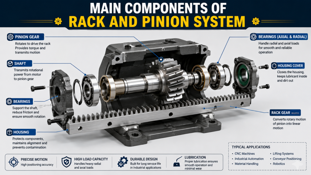
1). Rack:
- The rack is the linear element. Teeth are cut to match the pinion’s tooth profile — typically involute. Racks come in straight-cut (spur) or helical configurations. Helical racks run quieter and handle higher loads but generate axial thrust forces that the bearing arrangement must manage.
2). Pinion:
- The pinion is a standard spur or helical gear. Smaller diameter means higher force output for a given torque but lower linear speed. Larger diameter gives higher speed but requires more torque to move the same load.
3). Shaft:
- The pinion mounts on a shaft supported by bearings. Shaft diameter, keyway design, and coupling selection directly affect torque transmission capacity and system reliability.
4). Bearings:
- Bearings support radial and axial loads from the pinion. In high-load or high-speed applications, angular contact bearings or tapered roller bearings are common. Poor bearing selection is a leading cause of premature rack and pinion failures in industrial machinery.
5). Housing:
- The housing positions the pinion relative to the rack, maintains gear mesh geometry, and protects internal components from contamination. In dirty environments — foundries, steel mills, aggregate handling — housing seal integrity is critical.
📘 Suggested Course: Facility Management – Operation, Maintenance & Services
👉 If you want to understand facility operations, maintenance strategies, and essential facility management services with real-world industrial applications, this course is highly recommended.
👉 Learn complete facility management fundamentals here: [https://trk.udemy.com/m4Ez0Z]
👉 Get full subscription access: https://trk.udemy.com/PzKGrq
Rack and Pinion Design Considerations:
Getting the design right upfront prevents expensive rework in production. Here are the factors that matter most on the engineering side.
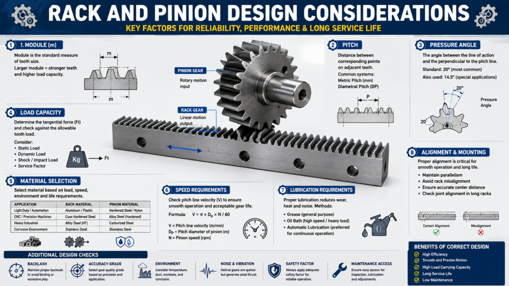
1). Gear Module:
- Module is the standard metric measure of tooth size. Larger module = larger, stronger teeth. Match the module of the rack to the pinion — mismatched modules will destroy both components fast.
2). Pitch:
- Circular pitch determines the spacing between teeth. In U.S. industrial applications, diametral pitch (DP) is still widely used. Higher DP = finer teeth. Lower DP = coarser, stronger teeth for heavy loads.
3). Pressure Angle:
- Most industrial rack and pinion systems use a 20° pressure angle. Some older or specialty systems use 14.5°. Never mix pressure angles between rack and pinion — even a close visual match will cause accelerated wear and noise.
4). Material Selection:
| Application | Rack Material | Pinion Material |
| Light-duty automation | Aluminum alloy | Hardened steel or nylon |
| CNC machines | Case-hardened steel (C45 or 42CrMo4) | Hardened alloy steel |
| Heavy industrial | Through-hardened alloy steel | Carburized and case-hardened |
| Corrosive environments | Stainless steel | Stainless steel or chrome-plated |
5). Load Capacity:
- Calculate both the tangential tooth load and the dynamic factor. Apply a service factor based on shock loading — impact loads in material handling or heavy manufacturing can exceed nominal loads by 2× or more.
6). Speed Requirements:
- High traverse speeds in CNC gantry systems push toward helical racks for smooth operation. Check the pitch line velocity and confirm it stays within the rated range for your gear quality grade.
7). Lubrication Requirements:
- Most industrial rack systems use an automatic lubrication system or periodic grease application. Pinion-mounted lubrication blocks are common in CNC and gantry applications. Under-lubrication is the single most common field failure cause — more on this in the maintenance section.
8). Alignment Considerations:
- Rack-to-pinion backlash and parallelism must be controlled. Most adjustable pinion mounts allow center distance adjustment. In long-travel systems using bolted rack sections, joint alignment is critical — a step or angular offset at a joint will cause impact loading every time the pinion crosses it.
📘 Suggested Course: Fundamentals of Reliability Engineering (Accredited)
👉 If you want to understand reliability engineering principles, failure analysis methods, and maintenance strategies with real-world industrial applications, this course is highly recommended.
👉 Learn complete reliability engineering fundamentals here: [https://trk.udemy.com/Ag3mGD]
👉 Get full subscription access: https://trk.udemy.com/PzKGrq
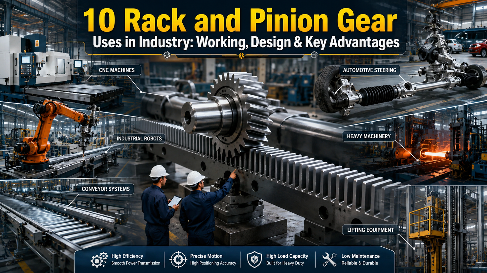
10 Rack and Pinion Gear Uses in Industry:
1). Automotive Steering Systems:
- How it’s used: The steering rack connects directly to the front wheel tie rods. When the driver turns the steering wheel, the pinion rotates and pushes or pulls the rack laterally, turning the wheels.
- Why rack and pinion is selected: It offers direct mechanical feedback (road feel), compact packaging, and predictable steering ratio. It replaced recirculating ball steering in most passenger vehicles by the 1980s.
- Common equipment examples: Nearly all modern passenger cars and light trucks. Power-assisted versions add hydraulic or electric actuators to reduce steering effort.
- Maintenance concerns: Rack seals and tie rod ends wear over time. A loose or clunking feel in the steering — especially over bumps — often signals worn rack bushings or a failing inner tie rod. In fleet maintenance shops, checking rack end play and boot condition during every alignment service is standard practice.
- Industrial notes: Electric power steering (EPS) systems use a motor-driven pinion or an electric assist motor acting on the steering column. Both still rely on the rack and pinion mechanism for final motion conversion.
2). CNC Machines:
- How it’s used: In CNC routers, plasma cutters, laser cutters, and large machining centers, rack and pinion drives handle axis travel — especially on long X and Y axes where ball screw length would create resonance or deflection problems.
- Why rack and pinion is selected: Ball screws have practical length limits, typically under 6 meters before resonance becomes a problem. Rack and pinion systems handle 10, 20, even 40-meter travel distances on gantry machines without those limitations. They also deliver high traverse speeds — 60+ meters per minute is common on CNC routers.
- Common equipment examples: Multicam routers, Messer plasma gantries, large-format laser cutting machines, heavy-duty bridge mills.
- Maintenance concerns: Lubrication is the top priority. Most CNC builders install automatic lubrication systems that meter grease directly to the pinion. Check lube delivery volume during every PM cycle. Worn pinion teeth show up as increased backlash in the axis — a compensation parameter in the controller can mask this for a while, but the physical wear continues.
- Industrial notes: High-precision applications use preloaded dual-pinion arrangements to eliminate backlash mechanically. This is standard on precision machining centers and aerospace parts production equipment.
📘 Suggested Course: DG Set Engineering – Design, Operation & Troubleshooting (13Hr)
👉 If you want to understand DG set design, operation principles, and troubleshooting techniques with real-world industrial applications, this course is highly recommended.
👉 Learn complete DG set engineering fundamentals here: [https://trk.udemy.com/dyVLq3]
👉 Get full subscription access: https://trk.udemy.com/PzKGrq
3). Material Handling Systems:
- How it’s used: Rack and pinion drives position transfer cars, shuttle tables, pallet systems, and work-holding fixtures across factory floors. A rack bolted to the floor or a beam guides a motorized car or carriage.
- Why rack and pinion is selected: Compared to chain drives or cable pulls, rack and pinion provides positive positioning with no slack accumulation. It handles side loads better than linear actuators in many configurations.
- Common equipment examples: Steel mill transfer cars, die change systems in stamping plants, pallet transfer lines in automotive body shops.
- Maintenance concerns: Floor-mounted rack installations accumulate debris — coolant, chips, scale, weld spatter. Cleaning frequency and rack cover design matter a lot in these environments. Tooth wear from contamination is a common failure mode.
- Industrial notes: In automotive plants, rack and pinion driven transfer cars move body stampings and dies that weigh 20 to 80 tons. The rack sections are precision aligned and bolted to the floor structure with torqued fasteners checked on a set PM interval.
4). Conveyor Positioning Systems:
- How it’s used: Rack and pinion drives position conveyor sections, diverters, and sorting gates in packaging, food processing, and distribution center lines. They also drive indexing tables that advance parts or products to workstations.
- Why rack and pinion is selected: The positive engagement means no slippage under load — important when you need a conveyor section to stop at an exact position 200 times per shift, every shift.
- Common equipment examples: Sortation conveyors in Amazon and FedEx distribution centers, indexing conveyors in automotive assembly plants, food-grade conveyor diverters.
- Maintenance concerns: In food-processing environments, stainless steel racks with food-grade grease are required. Standard steel racks will corrode and contaminate product. Tooth pitch wear shows up as positioning drift — the carriage stops slightly past or short of target.
- Industrial notes: Many conveyor OEMs run rack and pinion positioning at much lower precision than CNC applications. Backlash compensation in the control system keeps positional accuracy acceptable through the wear cycle.
📘 Suggested Course: Pump and Motor Basics, Selection and Optimization (HVAC)
👉 If you want to understand pump and motor fundamentals, proper equipment selection, and optimization techniques with real-world HVAC applications, this course is highly recommended.
👉 Learn complete pump and motor system fundamentals here: [https://trk.udemy.com/xJ5yq3]
👉 Get full subscription access: https://trk.udemy.com/PzKGrq
5). Industrial Robots:
- How it’s used: Rack and pinion drives extend the work envelope of stationary robot arms. A robot mounted on a linear track — called a seventh axis — uses rack and pinion to travel along the track, allowing the arm to service multiple workstations or longer weld lines.
- Why rack and pinion is selected: High force capacity, robust construction, and low maintenance relative to linear motors at the load ratings required for robot travel axes. Also far more cost-effective than linear motor systems for most track lengths.
- Common equipment examples: KUKA KL series linear tracks, FANUC track units, Yaskawa extended reach systems in automotive welding lines.
- Maintenance concerns: Robot track racks operate in weld spatter environments. Spatter accumulation on rack teeth causes impact loading on the pinion. Regular cleaning and replacement of spatter guards is part of robot PM programs in welding cells.
- Industrial notes: Track length in automotive plants often ranges from 6 to 20 meters. The racks are precision-aligned sections, and joint offsets cause detectable axis vibration at speed — measurable in robot path accuracy data.
6). Railway Switching Mechanisms:
- How it’s used: Rack and pinion mechanisms drive railway switch machines — the actuators that physically move the rail switch blades from one position to another. The pinion-driven mechanism translates the motor rotation into the lateral throw distance required to move the switch.
- Why rack and pinion is selected: Positive, non-slip engagement means the switch locks firmly in position under load from passing train wheels. The mechanism is self-locking in some configurations, adding a passive safety element.
- Common equipment examples: American Switch and Signal (now Ansaldo) electric switch machines, rail yard control systems in major U.S. freight hubs.
- Maintenance concerns: Switch machines operate outdoors in all weather. Lubrication with low-temperature grease is required for cold climates. Contamination with ballast and ice is a chronic maintenance problem. Inspection cycles are short compared to most industrial equipment — federal rail safety regulations drive the PM schedule.
- Industrial notes: A single rack and pinion switch failure that leaves a switch in an indeterminate position can result in a derailment. Redundant position detection and frequent inspection are non-negotiable.
📘 Suggested Course: Reciprocating Compressors – Principles, Operation & Design
👉 If you want to understand reciprocating compressor working principles, operation methods, and design concepts with real-world industrial applications, this course is highly recommended.
👉 Learn complete reciprocating compressor fundamentals here: [https://trk.udemy.com/ZVKXe0]
👉 Get full subscription access: https://trk.udemy.com/PzKGrq
7). Packaging Machinery:
- How it’s used: In filling machines, form-fill-seal equipment, carton erectors, and labeling systems, rack and pinion drives position heads, platens, and guides with precision and repeatability.
- Why rack and pinion is selected: Clean-room-compatible versions exist in stainless steel with sealed housings. High cycle rates — some packaging machines run 200+ cycles per minute — require low backlash and consistent positioning throughout the shift.
- Common equipment examples: Bosch Packaging (now Syntegon) filling lines, ULMA form-fill-seal machines, Marchesini carton-handling systems.
- Maintenance concerns: At high cycle rates, wear accumulates quickly. Tooth surface condition on the pinion is a good leading indicator — pitting or surface fatigue shows up before significant backlash develops. Lubrication intervals in high-speed packaging are much shorter than in heavy industrial applications.
- Industrial notes: Pharmaceutical packaging runs under FDA production standards. All lubrication materials in food-contact or pharmaceutical zones must be NSF H1 rated. Using general industrial grease in these areas is a regulatory violation.
8). Lifting Equipment:
- How it’s used: Rack and pinion drives power vertical lifting in construction hoists, personnel lifts, and rack-and-pinion elevators used in high-rise construction. The rack mounts on a vertical mast; the pinion-equipped drive carriage climbs or descends the rack.
- Why rack and pinion is selected: Unlike cable hoists, rack and pinion lifts don’t rely on friction between rope and drum. The positive tooth engagement provides a mechanical position lock and controlled descent even under power failure with a braking pinion arrangement.
- Common equipment examples: Alimak construction hoists, Maber rack-driven personnel lifts, Scanclimber facade access systems. Used extensively on job sites building high-rises across U.S. cities.
- Maintenance concerns: Rack sections on construction hoists take significant abuse — weather exposure, impact from loading, and accumulation of concrete and debris. Worn rack sections must be replaced; they can’t be field-repaired. Daily visual inspection of rack tooth condition before personnel use is a safety requirement.
- Industrial notes: OSHA 1926.552 governs construction hoist inspection requirements. Rack and pinion personnel hoists require a competent person inspection before each shift. This is not optional.
📘 Suggested Course: CMRP Exam Full Preparation Course + Full Mock Exam (110 Q&A)
👉 If you want to prepare for the CMRP exam with structured lessons, practice questions, and realistic mock exams to strengthen your maintenance and reliability knowledge, this course is highly recommended.
👉 Learn complete CMRP exam preparation concepts here: [https://trk.udemy.com/3kZjqy]
👉 Get full subscription access: https://trk.udemy.com/PzKGrq
9). Automation Systems:
- How it’s used: In industrial automation and assembly lines, rack and pinion drives move slides, transfer units, and pick-and-place mechanisms along programmed paths. Servo motor driven pinions with precision racks are the standard for high-throughput automation.
- Why rack and pinion is selected: Servo-controlled rack and pinion systems offer high dynamic performance — fast acceleration, controlled deceleration, and position repeatability under 0.05mm in quality installations. Ball screws become impractical at the stroke lengths common in automation.
- Common equipment examples: HIWIN rack and pinion actuator modules, Bosch Rexroth precision rack systems, Parker Hannifin linear drive systems used across U.S. automotive and electronics manufacturing plants.
- Maintenance concerns: Servo-driven rack systems should be monitored for following error increases — a trend toward higher following error at a given load indicates mechanical wear or lubrication degradation. Modern servo drives log this data; use it.
- Industrial notes: In predictive maintenance programs, vibration signatures at the rack joint frequency can detect rack wear before it reaches a point of causing positioning failures. This is a standard feature in condition monitoring platforms used in advanced manufacturing facilities.
10). Heavy Manufacturing Equipment:
- How it’s used: Large planer mills, floor borers, bridge cranes, and heavy press feed systems use rack and pinion drives for primary axis motion. These are machines where strokes run 5 to 30+ meters and loads are measured in metric tons.
- Why rack and pinion is selected: At large scales and loads, rack and pinion is often the only practical mechanical solution for controlled linear positioning. Hydraulic cylinders can’t provide accurate positioning over these strokes. Ball screws of this size are prohibitively expensive and prone to thermal growth problems.
- Common equipment examples: Giddings & Lewis floor-type horizontal boring mills, large-bed planer mills in shipbuilding and bridge fabrication shops, crane bridge travel drives at steel mills and heavy fabricators.
- Maintenance concerns: Rack tooth wear at the end of travel — where the carriage reverses — is typically the first wear location because that’s where the most load reversals happen. Periodic rack inspection with a go/no-go tooth wear gauge is the right approach. Waiting for audible noise or positioning error to trigger maintenance is too late.
- Industrial notes: In steel mill environments, fine metallic particles from grinding and cutting operations are extremely abrasive. Rack covers and wipers on the carriage reduce contamination, but they require regular inspection and replacement.
📘 Suggested Course: Shaft Alignment – Principles and Best Engineering Practices
👉 If you want to understand shaft alignment principles, alignment methods, and best engineering practices with real-world industrial applications, this course is highly recommended.
👉 Learn complete shaft alignment fundamentals here: [https://trk.udemy.com/7XOy9V]
👉 Get full subscription access: https://trk.udemy.com/PzKGrq
Key Advantages of Rack and Pinion Gear:
| Advantage | Industrial Benefit |
| High load capacity | Handles multi-ton loads in heavy manufacturing and material handling |
| Unlimited stroke length | No practical travel limit — ideal for gantry machines and transfer systems |
| High positioning speed | Traverse rates of 60+ m/min achievable in CNC and automation applications |
| Positive engagement | No slippage under load; reliable positioning in critical applications |
| Bidirectional operation | Full force in both directions without system modification |
| Simple maintenance | Accessible, inspectable, and serviceable with standard tools |
| High efficiency | Typical efficiency of 90–95% in well-maintained systems |
| Scalable design | Same mechanism scales from small packaging machinery to large bridge mills |
| Cost-effective at long strokes | Significantly lower cost than ball screws or linear motors at long travel lengths |
| Compact force generation | High force output relative to mechanism size and weight |
Common Failure Problems and Maintenance Tips:
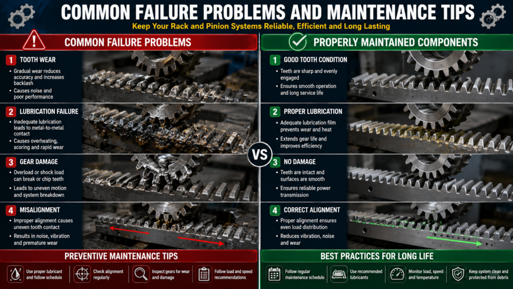
1). Gear Wear:
- Problem: Progressive tooth wear increases backlash and reduces positioning accuracy.
- Cause: Inadequate lubrication, abrasive contamination, or overloading.
- Maintenance tip: Inspect pinion tooth flanks at each PM. Use a tooth wear gauge for quantitative tracking. Replace pinion before the rack — pinions are cheaper and wear faster due to higher contact frequency.
2). Misalignment:
- Problem: The pinion axis is not parallel to the rack. Contact is concentrated on one edge of the tooth, causing rapid wear and noise.
- Cause: Initial setup error, housing wear, or structural deflection under load.
- Maintenance tip: Check mesh contact pattern with layout blue (Prussian blue compound) during commissioning and after any major structural work. Edge contact is an immediate corrective action item.
3). Lubrication Failure:
- Problem: Metal-to-metal contact causes rapid surface fatigue, scoring, and tooth failure.
- Cause: Automatic lube system blockage, wrong grease viscosity, or missed manual lubrication intervals.
- Maintenance tip: Verify lube delivery volume monthly on automatic systems — many techs confirm the system is “running” but never check actual output. Cold temperatures thicken grease and can block delivery lines.
4). Excessive Backlash:
- Problem: Free play in the drive direction causes positioning error and can cause impact loading on direction reversal.
- Cause: Tooth wear, worn pinion shaft bearings, or excessive center distance.
- Maintenance tip: Check backlash with a dial indicator at the pinion shaft. Compare to OEM specification. In servo systems, backlash compensation parameters should be adjusted to match current mechanical backlash — leaving the parameter unchanged as the mechanism wears masks the problem in motion but causes hidden impact loads.
5). Tooth Damage:
- Problem: Broken or chipped rack or pinion teeth cause immediate loss of function and potential secondary damage.
- Cause: Single overload event, foreign object ingestion, or brittle failure from low-temperature operation without cold-temperature grease.
- Maintenance tip: Conduct a root-cause analysis before replacing components. Replacing a damaged rack section without identifying the cause leads to repeat failure. Check for hardness and material certifications when sourcing replacement rack sections — off-spec replacement parts are a documented issue with low-cost rack suppliers.
📘 Suggested Course: Centrifugal Compressors – Principles, Operation and Design
👉 If you want to understand centrifugal compressor working principles, operational concepts, and design fundamentals with real-world industrial applications, this course is highly recommended.
👉 Learn complete centrifugal compressor engineering concepts here: [https://trk.udemy.com/9VzAjY]
👉 Get full subscription access: https://trk.udemy.com/PzKGrq
Rack and Pinion Selection Checklist:
Use this checklist before specifying a rack and pinion system on a new machine or retrofit project:
- Define stroke length: Total travel distance including overtravel allowance
- Calculate peak load: Include dynamic (acceleration) loads and apply service factor for shock
- Determine speed requirement: Maximum traverse speed and typical operating speed
- Select gear module and pitch: Based on load and speed; confirm availability from your supplier
- Choose pressure angle: 20° for standard industrial; confirm matching rack and pinion
- Select material: Match material to environment (temperature, moisture, chemical exposure, contamination)
- Specify surface hardness: Case-hardened or through-hardened based on load and wear requirements
- Design lubrication system: Automatic or manual; specify grease grade for operating temperature range
- Plan alignment provisions: Adjustable mount for center distance setting; shimming provisions for rack joint alignment
- Specify backlash requirement: Preloaded dual-pinion for zero-backlash; standard single pinion with electrical compensation for general use
- Address contamination protection: Rack covers, wiper seals, and carriage seals for dirty environments
- Confirm safety requirements: OSHA, ANSI, or application-specific safety standards (construction hoists, rail, pharmaceutical)
- Plan inspection access: Can maintenance personnel inspect tooth condition and check lubrication delivery without major disassembly?
Frequently Asked Questions:
Q1: What is the main difference between a rack and pinion and a ball screw for linear motion?
- Ball screws offer higher positional accuracy and efficiency at short to medium stroke lengths (typically under 4–6 meters). Rack and pinion systems are better suited for long strokes, high traverse speeds, and high thrust loads. In U.S. machine tool and industrial automation applications, ball screws dominate precision grinding and turning centers, while rack and pinion is the standard for large CNC routers, gantry systems, and transfer equipment.
Q2: What causes backlash in a rack and pinion system?
- Backlash is the free movement in the drive direction before the pinion engages the rack on reversal. It comes from tooth wear, increased center distance from worn bearings or housing, or initial design clearance. In precision systems, preloaded dual-pinion arrangements eliminate mechanical backlash. In general industrial systems, electronic backlash compensation in the servo controller handles it within the wear tolerance range.
Q3: How often should rack and pinion systems be lubricated?
- That depends heavily on the application. CNC routers with automatic lube systems typically meter grease every few hours of operation. Manual lube intervals in heavy industrial equipment might be daily to weekly depending on load, speed, and contamination level. Follow OEM recommendations as a baseline, then adjust based on field observation of grease condition at the inspection interval.
Q4: Can rack and pinion gears handle vertical loads?
- Yes. Rack and pinion systems are used extensively in vertical lifting applications — construction hoists, personnel lifts, and vertical transfer systems. For vertical applications, a brake or secondary holding mechanism is typically required so the load doesn’t back-drive the system under power loss. The rack geometry in vertical systems must account for the full dead weight of the carriage plus live load in the drive design.
Q5: What is the typical efficiency of a rack and pinion system?
- Well-maintained rack and pinion systems with proper lubrication run at 90–95% mechanical efficiency. Efficiency drops with tooth wear, misalignment, and lubrication deficiency. Helical rack systems have slightly lower efficiency than spur rack due to the axial thrust component, but the improvement in noise and load distribution usually outweighs the efficiency penalty in industrial applications.
Q6: How do you measure rack and pinion wear in the field?
- The most practical field methods are: (1) dial indicator measurement of backlash at the pinion shaft against OEM specification; (2) visual inspection of tooth flanks for pitting, scoring, or profile wear; (3) tooth wear gauge against a new tooth profile template; and (4) servo drive following error trend analysis in digitally controlled systems. Don’t wait for audible noise — that usually means significant wear has already occurred.
Q7: What is the difference between spur and helical rack and pinion systems?
- Spur racks have teeth cut perpendicular to the rack length. They’re simpler to manufacture, easier to align, and generate no axial thrust force. Helical racks have angled teeth, which increases the contact ratio (more teeth sharing load at any instant), reduces noise and vibration, and increases load capacity. Helical racks require bearing arrangements that handle the axial thrust component. For high-speed CNC and precision automation, helical is the standard. For simpler material handling and positioning, spur rack is acceptable and lower cost.
Conclusion:
Rack and pinion gear uses cover an enormous range of industrial equipment — from the steering rack on a delivery truck to the drive axis of a 30-meter gantry machine. The mechanism is durable, serviceable, and well-understood by every qualified mechanical maintenance tech. Key factors that determine performance in service are proper lubrication, controlled alignment, correct material specification for the environment, and consistent inspection. Get those four things right, and a rack and pinion system will run reliably for years in demanding industrial service.